Product Visualization
How to prepare a CAD file for product rendering
The five things that decide whether your CAD file becomes finished product imagery in a week or a fortnight, from a studio that opens these files every day.
6 min read
Product Visualization
The five things that decide whether your CAD file becomes finished product imagery in a week or a fortnight, from a studio that opens these files every day.
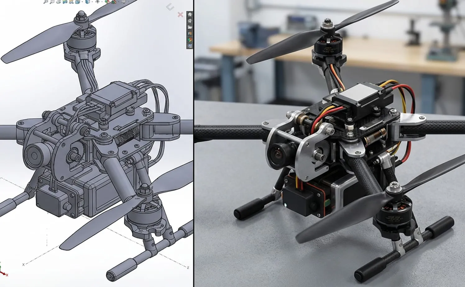
Most of the delay in a product visualization project happens before anyone opens a 3D application. It happens in the hour after your CAD file arrives, when we find out what is actually in it.
None of what follows is difficult. It is rarely thought about, because the file was built to be manufactured rather than photographed, and those are two different jobs with two different sets of requirements.
Engineering tolerates gaps. A surface that stops a hundredth of a millimetre short of its neighbour still machines correctly, because the machine works from the toolpath rather than the shell. A renderer does not tolerate it. Light has to bounce off a continuous surface, and where the surface is open the light travels inside the object and comes back wrong, usually as a dark seam along an edge that should be catching a highlight.
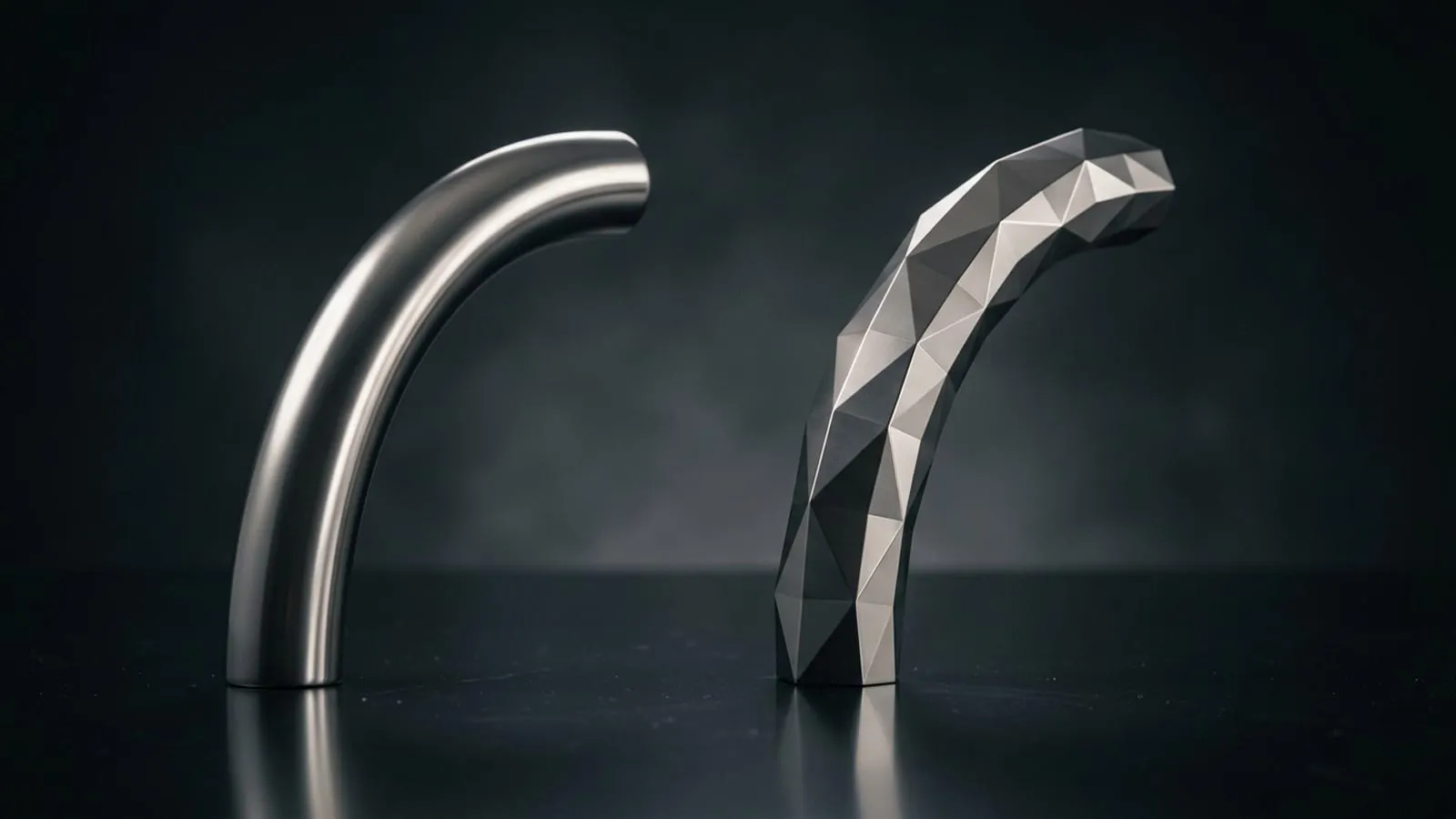
Every CAD model has to be converted to polygons before a GPU can draw it, a step called tessellation. Two parameters govern how good that conversion is: chord error, the largest gap allowed between the true surface and the flat triangle standing in for it, and maximum angle, which controls how many triangles get spent on a tight fillet (Pixyz, tessellation documentation).
This is the whole argument for sending a STEP file rather than an STL. A STEP carries the underlying boundary representation, so tessellation happens on import and we choose those two numbers, against the camera distance the shot actually uses. An STL has already been tessellated by whoever exported it, at whatever settings their dialog defaulted to. If that was coarse, a curve arrives faceted and there is no way back: the mathematics that described the curve was discarded at export.
It is worth knowing this is a genuinely hard problem rather than a tooling preference. Converting boundary representations into valid meshes remains fragile, because the curve intersections in the original have to be approximated (Journal of Computational Design and Engineering, 2026). Giving us the original geometry means the approximation happens once, under control, rather than twice.
Send: STEP or a native file. Avoid: STL, unless it is all that exists.
An assembly modelled in millimetres and exported as though it were inches arrives twenty-five times too large. That is easy to spot. What is not easy is a sub-assembly carrying a different unit setting from its parent, so one bracket is right and the fastener through it is not.
Depth of field is what exposes it. Camera optics are simulated at real-world scale, so an object at the wrong size focuses like an object of that wrong size. A handheld product photographed with the depth of field of a building looks subtly, unplaceably wrong long before anyone works out why.
Labels, printed panels and packaging should arrive as their own files, vector where possible and at print resolution otherwise, rather than baked into a texture already applied to the geometry.
Two reasons. Artwork that exists separately can be swapped for a colourway or a language without touching the model, which is most of the argument for rendering over photography in the first place. And embedded artwork has almost always been compressed already, so it holds up on a product page and falls apart the moment the camera moves closer.

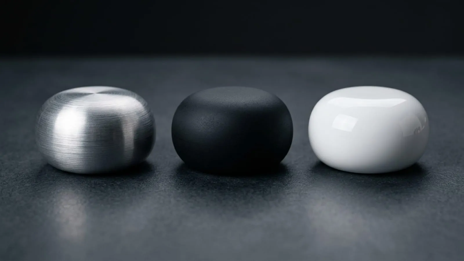
CAD files carry appearance data, and it is almost never right. A part arrives tagged “steel” when it is anodised aluminium, or “plastic” when it is a soft-touch coating with a very particular sheen.
Worth being precise about why: the STEP format is built to exchange engineering information and does not carry visual appearance at all, so anything about colour, gloss or texture has to be authored after import regardless of how the file was tagged. A dimensionally perfect model in the wrong material reads as a render immediately, whereas a slightly simplified model in the right one reads as a photograph. A finish name, a Pantone reference, or a phone photo of the sample in daylight is enough.
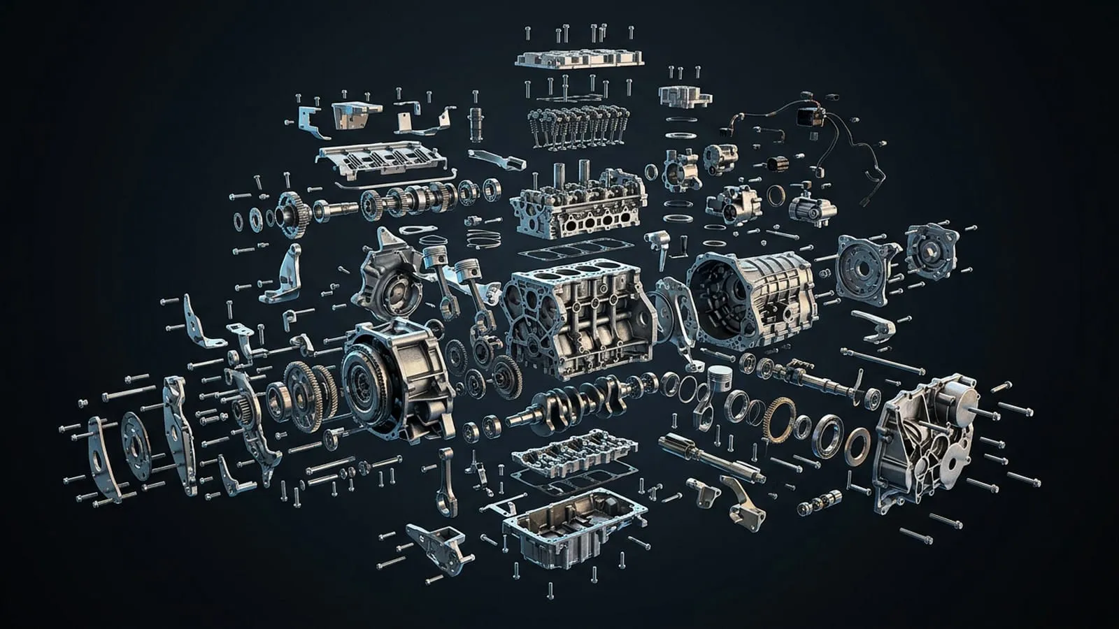
Manufacturing assemblies are complete: every screw, every internal rib, every bracket behind the housing. A full assembly can run to tens of thousands of parts, and the overwhelming majority sit behind something opaque.
You do not need to strip them out. We do that, and we would rather have the complete file than a version simplified by guesswork. But a 4 GB assembly takes a while to open, and telling us which sub-assemblies are visible saves more time than anything else on this list.
Plenty of clients do not, particularly for products that predate the current team. Dimensioned drawings work. A physical sample photographed from six angles with a handful of measurements works. It adds a couple of days at the modelling stage and nothing else changes.
The one thing that does not work is a single product photo with no dimensions. Not because it is too little to model from, but because it is too little to model accurately from, and a render that is five per cent wrong in proportion is worse than no render at all. It will be compared against the real product by someone holding one.
Send the file you have. We would rather look at a messy real assembly than wait for a tidy one.
But if you want the shortest path from file to finished imagery: a solid-body STEP in the correct units, artwork as separate vectors, a note on the finishes, and a line about which parts are visible. That combination has never once needed a follow-up email.
Send us your CAD files, a sketch, or just a description of what you are building, and tell us how far you need it taken. We come back with a fixed quote and a date.